Introduction to Shut Off Valve Mechanisms
Shut off valves are essential components in fluid control systems across residential, commercial, and industrial environments. They regulate the flow of liquids or gases by opening, closing, or restricting passage within a pipeline. Although shut off valves serve the same fundamental purpose, their internal mechanisms differ significantly depending on whether they are manual or automatic. Understanding these differences is valuable for engineering design, maintenance planning, and system integration. The choice between manual and automatic mechanisms often depends on operational demands, safety requirements, accessibility, response time expectations, and integration with control systems.
Manual shut off valves rely entirely on human input for operation. The operator physically turns, lifts, pushes, or twists a control element that engages the internal components responsible for flow control. In contrast, automatic shut off valves utilize powered actuators or self-contained mechanical systems that respond to signals, pressure changes, or environmental conditions. This article explores the internal mechanisms of both types, focusing on structure, functionality, driving force, control elements, and performance characteristics. Tables are included to organize technical comparisons and highlight design distinctions.
Internal Structure of Manual Shut Off Valves
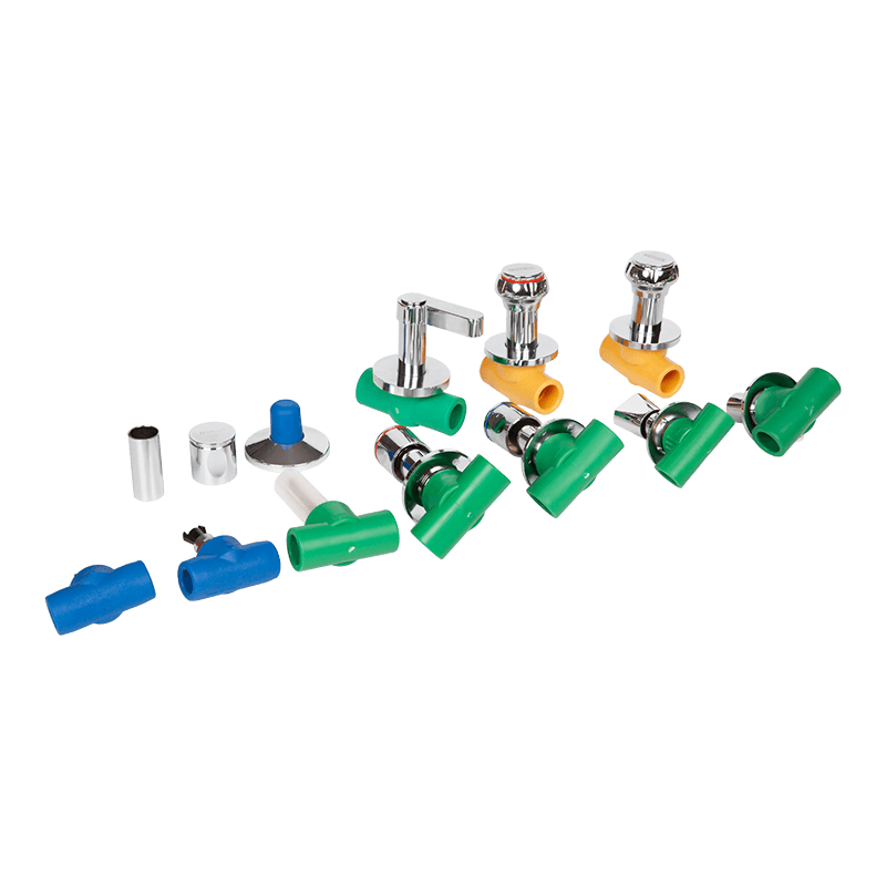
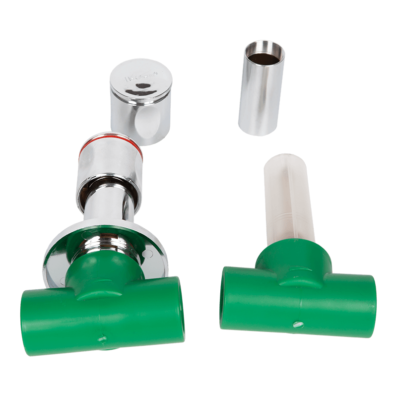
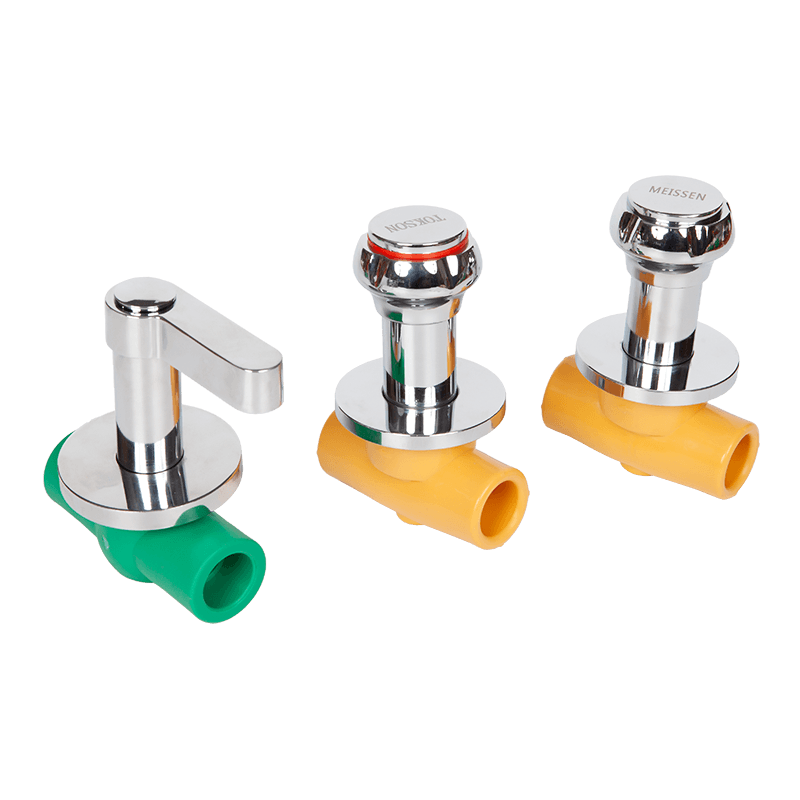
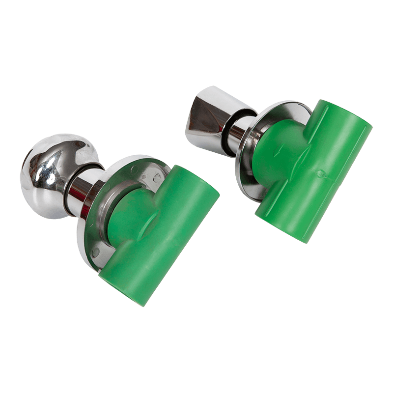
Manual shut off valves typically include a housing or body, a flow passage, a movable closure element such as a disc, ball, gate, or plug, and an external handle or wheel that transmits force internally. When the operator turns the handle, the movement is transferred through a stem or spindle into the valve body. The stem connects to the closure element, which shifts its position to control the flow. The design is straightforward and relies on mechanical linkage between the handle and the flow restriction or sealing component.
Because manual shut off valves require direct physical engagement, the stem is often threaded. As the operator rotates the handle, the threaded interaction moves the closure element linearly or rotationally. For example, in a gate valve, the gate rises or lowers as the stem rotates. In a ball valve, the stem rotates the ball with a drilled passage, aligning it with the pipeline or turning it perpendicular to interrupt the flow. The internal mechanism does not contain powered components, sensors, or electronic circuits. Instead, the mechanical forces generated by the operator provide the torque or linear force needed to move the internal parts.
Internal Structure of Automatic Shut Off Valves
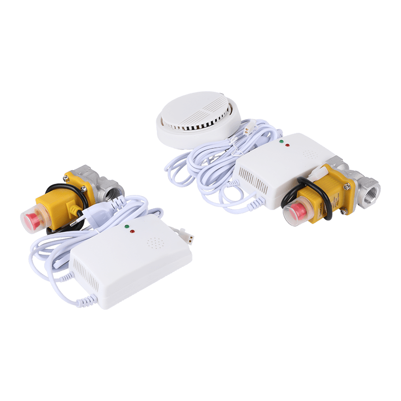
Automatic shut off valves incorporate an actuator that replaces or supplements manual input. The actuator may be powered by electricity, compressed air, hydraulic fluid, magnetic systems, or spring-loaded assemblies. The actuator attaches to the valve stem or internal shaft in a manner that allows controlled movement of the closure element. Instead of relying on a handle or wheel, the actuator responds to external signals such as remote commands, system pressure fluctuations, temperature shifts, or emergency triggers.
Actuators are usually either rotary or linear, depending on how they must interact with the internal closure element. A rotary actuator might turn the stem of a ball valve. A linear actuator might push or pull a stem on a globe valve. The internal mechanism of the actuator includes gears, pistons, diaphragms, springs, or motors. When the actuator receives an input, it engages these components to move the closure element. The body design is usually sealed to protect the internal mechanism from dust, moisture, and media exposure. Automatic shut off valves may also include sensors, wiring channels, and feedback switches that confirm position or report operational status.
Comparison Table: Core Components
Below is a table outlining key differences in internal components between manual and automatic shut off valves:
| Aspect | Manual Shut Off Valve | Automatic Shut Off Valve |
|---|---|---|
| Primary Force Source | Human operation via handle or wheel | Actuator driven by electric, pneumatic, hydraulic, or mechanical force |
| Internal Movement | Direct linkage through stem and threads | Actuator transfers power to stem or shaft |
| Additional Components | Minimal, often only the valve body and stem | Actuator body, gears, springs, or pistons |
| Control Signals | Operator action only | Remote commands, sensors, or automated controls |
| Feedback Mechanism | Visual or tactile confirmation | Position indicators, switches, or sensors |
Driving Force and Motion Transfer in Manual Designs
The driving force in manual shut off valves is derived from physical rotation or movement of the handle or wheel. The motion transfer is straightforward: the handle connects to a stem that either threads into the bonnet or body to produce vertical motion, or rotates freely to turn internal elements. The threads, packing, and seals must be dimensioned to maintain reliability over repeated use. Mechanical advantage is often achieved through the diameter of the handle or wheel. Larger handles reduce the torque required but do not alter the internal complexity significantly.
Another feature of manual designs is the tactile feedback provided to the operator. As the handle is turned, resistance can be sensed if debris obstructs movement or if the closure element has reached its seat. The internal mechanism does not have built-in automatic compensation for torque variations. Maintenance typically involves lubrication of threads, inspection of seals, and occasional replacement of internal parts if wear or corrosion is detected. The simplicity of motion transfer makes manual shut off valves accessible in many low-frequency or low-automation settings.
Driving Force and Motion Transfer in Automatic Designs
Automatic shut off valves employ actuators that apply force to the stem or closure element. In electric actuators, a motor produces rotary motion that may be translated into linear movement through gears or cam mechanisms. Pneumatic actuators use compressed air to push a piston or diaphragm. Hydraulic actuators work similarly but with fluid under pressure. The motion transfer requires coordinated internal components such as linkages, springs, or seals to manage pressure and ensure controlled movement.
In some designs, the actuator includes a fail-safe mechanism. For example, a spring-return actuator might automatically close the valve if power or pressure is lost. This aspect influences how the internal mechanism is arranged, since the spring or diaphragm must be housed within the actuator body. Motion transfer may include limit switches that engage once the closure element reaches the open or closed position. These switches provide signals to a control system without additional manual checks.
Control and Feedback Considerations
Manual shut off valves rely mainly on the operator’s judgment and observation. Position is determined by how far the handle has been turned. Some valves include visual indicators such as arrows or position markers, but these are simple attachments that do not alter the basic design. The internal mechanism remains a direct mechanical linkage without internal sensors or wiring paths.
Automatic shut off valves can incorporate internal or external position indicators, wiring for remote status reporting, and control modules that interpret signals. The internal mechanism may include microswitches, magnetic sensors, or encoders to track the valve’s position. These additions do not alter the fundamental closure element but do change how the system monitors operation. The interplay between the actuator and these sensors influences how the closure element moves and stops. The valve body must accommodate or align with these features to ensure accurate responses.
Maintenance Implications
The internal mechanism of manual shut off valves is more straightforward, which can simplify maintenance. Maintenance staff typically inspect stems, packing, seals, and threads. Minimal moving parts reduce internal complexity, making it easier to diagnose leaks or operational stiffness. Replacement parts usually involve seat rings, O-rings, or gland packing. As long as the internal surfaces remain intact, the valve can continue functioning reliably.
Automatic shut off valves require attention to both the valve body and the actuator. The internal mechanism includes additional seals, gaskets, moving pistons, gears, or springs. Maintenance may involve disassembly of the actuator, checking for wear on internal seals, verifying sensor alignment, and ensuring consistent power supply or pressure. When an automatic valve is integrated into a larger control system, maintenance procedures also include verification of communication lines or wiring. The enhanced functionality and remote operation bring the advantage of controlled actuation but increase the scope of internal components requiring attention.
Operational Characteristics in Different Environments
Manual shut off valves are often preferred where power sources are unavailable or where budget constraints guide selection. In remote installations or where access is straightforward, a manual approach can suffice. The internal mechanism is robust in many standard applications, and the absence of powered components reduces vulnerability to electrical or pneumatic failure. However, the mechanism still depends on direct physical action, and sudden closure or opening can be limited by the operator’s speed and torque application.
Automatic shut off valves suit environments where rapid response, remote control, or integration with automation systems is important. Their internal design allows them to operate even if the operator is not physically present. The actuator can respond to pressure drop, temperature change, or emergency signals that trigger immediate closure. The internal mechanism must manage quick transitions and ensure repeatable performance. While the initial setup can be more involved due to wiring or air supply arrangements, the long-term gain lies in reduced manual intervention and improved system coordination.
Performance Comparison Table
The table below summarizes performance-related contrasts stemming from internal mechanism design:
| Feature | Manual Shut Off Valve | Automatic Shut Off Valve |
|---|---|---|
| Operating Speed | Depends on user input | Typically faster and more consistent |
| Remote Capability | Not inherently available | Often integrated through control signals |
| Internal Complexity | Lower, mainly stem and closure element | Higher, includes actuator internals and sensors |
| Maintenance Scope | Stem, packing, sealing surfaces | Valve body plus actuator components |
| Failure Modes | Thread wear, seal leakage | Actuator malfunction, signal loss, seal wear |
Adaptability and Scalability
The internal mechanism of a manual valve can be adapted with lever extensions, locking devices, or position indicators, but these additions remain external. The core internal arrangement does not change significantly. Scalability is limited by human operation. In contrast, automatic shut off valves can incorporate a range of actuators with varying torque or thrust capacities. The valve body can remain similar while the actuator changes based on system requirements. This adaptability in the internal mechanism design extends the usability across different pipeline sizes, pressures, and media types.
Scalability also involves system upgrades. For manual designs, upgrading often means replacing the entire valve or adding an external actuator. Automatic versions can facilitate upgrades through actuator replacement or reconfiguration. The internal mechanism of the actuator can be chosen or modified to provide higher closing torque or a faster response. These internal features allow the same valve body platform to serve multiple operational roles.
Energy Source and Influence on Internal Components
In manual shut off valves, the energy source is the operator’s effort, so internal components are sized for manageable torque and minimal mechanical friction. Seals and packing materials are selected to minimize leakage while allowing smooth stem movement. In automatic valves, the actuator’s energy source may require additional internal elements, such as pistons or electromagnets. These components add to the size and complexity of the mechanism. Energy delivery also influences how the closure element seats and unseats, as some actuators apply consistent force throughout the stroke. This factor affects internal wear and alignment over time.
Another consideration is environmental compatibility. Certain environments may limit or prohibit electric actuators due to hazards. In those cases, pneumatic or spring-return designs might be chosen. The internal mechanism adapts by using specific seals, diaphragms, or materials compatible with the actuating medium. Each variant modifies how force is generated and transmitted inside the actuator housing.
Integration with System Controls
Manual shut off valves inherently operate independently of system controls. They do not integrate with automation networks or process control software. The internal mechanism does not include ports, channels, or mounting points for sensors or wiring. In contrast, automatic shut off valves are designed with integration in mind. Internal cavities or external brackets may accommodate position switches, feedback wiring, or pneumatic fittings. The actuator housing often has designated entry points for cables or tubing. This design aligns with logic controllers or safety systems that require precise valve positioning.
The internal arrangement of gears or pistons must coordinate with these control elements to ensure correct response and feedback. In electrically actuated valves, internal limit switches can detect the open or closed position. When triggered, these switches signal the control system to halt the motor. This closed-loop arrangement provides control over the internal mechanism and helps prevent overtravel or mechanical strain.
Inspection and Troubleshooting
Manual shut off valves can be inspected by observing handle movement and checking for internal leaks. Troubleshooting often involves dismantling the bonnet or removing the stem assembly to access the closure element and seals. The internal mechanism is accessible and easy to understand due to its simplicity. Replacement parts do not typically require specialized knowledge.
Automatic shut off valves demand more detailed inspection of actuators, connection points, and signal paths. If the valve fails to open or close, maintenance staff must evaluate the actuator’s internal condition. This may involve checking for actuator motor issues, piston seal degradation, or misalignment of gears. Some actuators include inspection ports or removable panels that provide limited viewing access to internal parts. Troubleshooting can also involve reviewing electrical connections or pneumatic pressure lines. The complexity necessitates documentation to guide disassembly and reassembly.

 LANGUAGE
  English
 русский
 中文简体
中文简体