Basic Working Principle of Water Pressure Relief Valves
Water pressure relief valves are critical safety components used in plumbing and hydraulic systems to prevent excessive pressure buildup. These valves automatically open when the internal pressure of a system exceeds a preset limit, allowing water to escape until pressure returns to a safe level. The primary mechanism relies on the balance between water pressure and the force exerted by a spring. When the system pressure remains within normal limits, the spring keeps the valve closed, sealing the outlet. However, when pressure increases beyond the threshold, the water force overcomes the spring tension, lifting the valve disc and releasing excess fluid. Once the pressure drops, the spring pushes the valve disc back into position, sealing the system again. This cyclical operation maintains stable pressure and prevents potential damage to pipes, fittings, and equipment.
Pressure Detection Mechanism
The ability of a water pressure relief valve to detect overpressure relies on a precisely calibrated spring or diaphragm system. The valve’s internal components are designed to respond proportionally to pressure changes within the pipeline. The spring is set to compress only when pressure surpasses a predetermined value, which is usually specified during system installation based on operating requirements. In some advanced models, a diaphragm separates the pressurized water from the spring chamber, allowing sensitive detection without fluid contamination. The valve body, often made from brass, stainless steel, or bronze, supports accurate and reliable detection even under fluctuating temperature and pressure conditions. Regular calibration ensures that the valve responds accurately to small deviations before the pressure reaches dangerous levels.
Structure and Key Components
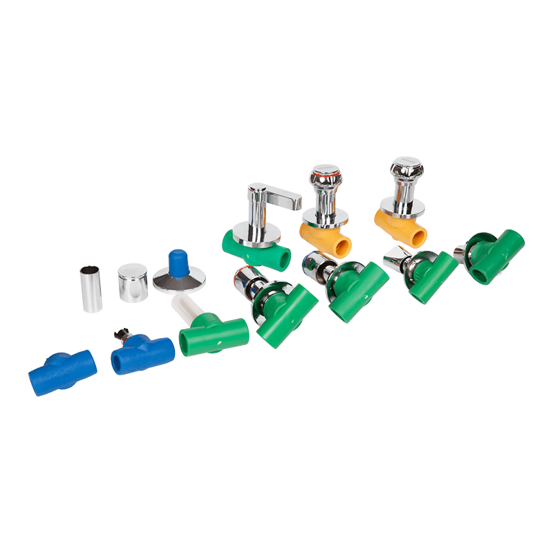
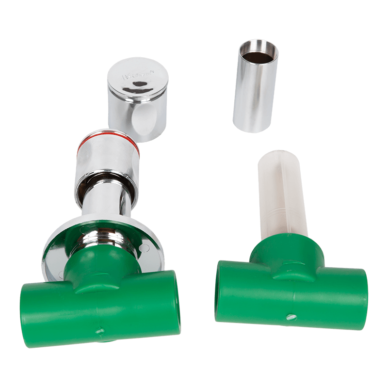
A water pressure relief valve consists of several major components working together to control system pressure effectively. These include the valve body, spring, adjustment screw, valve seat, disc, and discharge outlet. The valve seat provides a sealing surface, while the disc controls the flow of water through the outlet. The spring is preloaded with tension adjusted by a screw or knob, which determines the pressure setting. When the pressure exceeds the set limit, the disc lifts off the seat, creating a pathway for water discharge. The discharged water flows through an outlet pipe directed to a safe drainage area. The internal geometry of these components ensures stable performance, reducing pressure spikes and maintaining smooth re-seating after discharge.
Types of Water Pressure Relief Valves
Water pressure relief valves come in several configurations depending on system design and application. Direct-acting valves are the most common type and use a simple spring-loaded mechanism. Pilot-operated valves, on the other hand, use a small auxiliary valve (pilot) that controls the opening of a larger main valve, making them more suitable for high-pressure or high-flow systems. Diaphragm-type valves employ flexible membranes that separate the fluid from mechanical parts, providing precise and contamination-free operation. The table below compares the characteristics of common types of pressure relief valves used in water systems.
| Valve Type | Operating Mechanism | Typical Application | Response Speed |
|---|---|---|---|
| Direct-Acting Valve | Spring directly opposes water pressure | Residential water systems | Moderate |
| Pilot-Operated Valve | Small pilot valve triggers main valve | Industrial and municipal systems | High |
| Diaphragm Valve | Flexible diaphragm detects pressure | Corrosive or sanitary environments | Fast |
Process of Pressure Relief
When pressure in a water system rises beyond the set limit, the relief valve responds automatically. The internal spring compresses as the valve disc lifts, allowing water to pass through the discharge outlet. The rate at which the valve opens depends on both the system’s pressure rise and the valve’s flow coefficient. In pilot-operated systems, the pilot valve first senses the overpressure, releasing a small volume of water to decrease the pressure on the main valve piston. This reduction in control pressure triggers the main valve to open fully. The valve remains open until pressure drops below the reseating threshold, at which point the spring reasserts force to close the disc against the seat. This precise mechanism ensures that only the required amount of water is released, preventing excessive fluid loss.
Factors Affecting Valve Performance
Several factors influence the accuracy and reliability of water pressure relief valves. These include spring material, corrosion resistance, installation orientation, and system fluid characteristics. High temperatures or aggressive water chemistry can alter material properties and reduce spring elasticity over time. Therefore, valves are often manufactured with stainless steel or other corrosion-resistant alloys. The installation angle must also align with manufacturer recommendations to ensure consistent pressure detection. Additionally, sediment or scale buildup inside the valve can obstruct the movement of internal components, leading to delayed or incomplete pressure relief. Regular inspection and maintenance are essential to ensure that the valve continues to operate correctly under varying system conditions.
Calibration and Setting Pressure Limits
Proper calibration ensures that a pressure relief valve opens at the desired pressure point. During installation, technicians use pressure gauges to verify that the valve responds accurately to the target setting. The adjustment screw at the top of the valve allows fine-tuning of the spring tension. For example, turning the screw clockwise increases spring compression and raises the opening pressure, while counterclockwise adjustment lowers it. Calibration should be performed with the system in a controlled state to avoid sudden discharges. Manufacturers provide recommended pressure settings based on system design parameters such as maximum operating pressure (MOP) and pressure relief ratio. Periodic recalibration is advised, especially for systems exposed to variable loads or temperature fluctuations.
Role of Temperature and Fluid Dynamics
Temperature and flow dynamics play a significant role in the performance of water pressure relief valves. As water temperature increases, its expansion rate and pressure rise accordingly, triggering the valve to relieve excess pressure. Thermal expansion in closed systems, such as water heaters, is a common cause of pressure fluctuations. In these cases, relief valves are specifically designed to handle both temperature and pressure variations. Fluid velocity also affects valve response; higher flow rates can cause rapid pressure spikes that demand quick reaction times. Engineers must consider these dynamic conditions when selecting and installing relief valves to ensure proper operation in real-world environments.
Safety Considerations in Valve Operation
Pressure relief valves play a crucial role in protecting both equipment and personnel. When installed in water supply or heating systems, they prevent catastrophic failures such as pipe bursts, gasket ruptures, or tank explosions. To maintain safety, valves should be tested regularly using manufacturer-approved procedures. Visual inspections help identify corrosion, leaks, or blockages. Any tampering with the spring setting without proper calibration tools can compromise system safety. Furthermore, discharge outlets should always be directed toward safe drainage areas to prevent injury or property damage. Incorporating pressure gauges and monitoring systems alongside the relief valve enhances safety by providing continuous feedback on system performance.
Maintenance and Testing Procedures
Regular maintenance ensures that water pressure relief valves function correctly throughout their service life. Maintenance typically includes cleaning, lubricating, and testing the valve. Sediment and mineral deposits should be removed from the valve seat and discharge path. In systems exposed to hard water, descaling treatments may be required. Functionality tests are conducted by manually lifting the test lever or gradually increasing system pressure to verify the valve’s opening point. If the valve fails to open or reseat properly, it should be replaced immediately. Keeping maintenance records helps track performance trends and identify potential deterioration before a critical malfunction occurs.
Common Problems and Troubleshooting
Water pressure relief valves can encounter issues such as leakage, chattering, or delayed opening. Leakage often occurs due to worn seals or foreign particles lodged between the valve seat and disc. Chattering, or rapid opening and closing, can result from improper pressure settings or turbulent flow conditions. A delayed opening response might indicate spring fatigue or mechanical obstruction. The table below summarizes common problems, their causes, and potential corrective actions.
| Problem | Possible Cause | Corrective Action |
|---|---|---|
| Leakage | Damaged seat, dirt, or corrosion | Clean or replace valve components |
| Chattering | Incorrect pressure setting or unstable flow | Recalibrate or stabilize system pressure |
| Delayed Opening | Spring fatigue or blockage | Inspect and replace spring or remove debris |
| Failure to Close | Deformed seat or weak spring | Replace seat or spring assembly |
Comparison of Relief Valve Applications
Different applications require different types of relief valves depending on pressure range, flow rate, and environmental conditions. For example, residential systems often use compact direct-acting valves, while industrial plants employ pilot-operated types for higher pressures. The table below outlines typical applications and selection factors.
| Application | Valve Type | Pressure Range | Key Consideration |
|---|---|---|---|
| Residential Water Heater | Direct-acting spring valve | 0.5–1.0 MPa | Temperature resistance and compact design |
| Municipal Water Supply | Pilot-operated valve | 1.0–3.5 MPa | High flow control and durability |
| Industrial Cooling System | Diaphragm-type valve | 0.8–2.5 MPa | Corrosion resistance and precision control |
Integration with Modern Monitoring Systems
Modern water systems often integrate pressure relief valves with digital monitoring technologies. Smart sensors detect pressure variations in real time and can alert operators to abnormal conditions. Some systems use automated control units to adjust valve settings or trigger secondary relief mechanisms if primary valves fail. Data from these sensors can be transmitted to central monitoring stations for predictive maintenance, reducing downtime and ensuring system reliability. This integration of mechanical safety devices with digital control systems represents a major advancement in fluid system management, improving both efficiency and safety.
Operational Reliability and Material Considerations
The long-term reliability of water pressure relief valves depends greatly on the materials used in their construction. Stainless steel and brass provide good resistance to corrosion and thermal expansion, while polymer-coated components offer protection against mineral buildup. For high-pressure systems, hardened alloys or composite materials are used to prevent deformation and maintain sealing integrity. Proper material selection ensures compatibility with the water chemistry and operating conditions, minimizing maintenance and maximizing operational lifespan. Manufacturers also perform endurance testing under simulated pressure cycles to confirm performance stability over thousands of opening and closing operations.

 LANGUAGE
  English
 русский
 中文简体
中文简体